Amiga SCART guide
Introduction
Last technical update March 2013
This article details how to build an Amiga RGB to SCART adaptor cable that will allow you to connect your
Amiga computer to a CRT or LCD TV. An explanation of the potential issues and the solution is provided
for the reader.
The design presented here tested with multiple LCD and CRT TVs.
Purchasing SCART cables
They are not available for sale from this website but the good folks at www.amigakit.co.uk manufacture SCART leads to this diagram.
This work is licensed under a Creative Commons Attribution 3.0 Unported License.
Background information on the Amiga RGB port
Before creating this cable I undertook a number of measurements on the Amiga video outputs.
The first issue I noticed was the voltage on the SYNC signal, it was 4.8V peak to peak, as shown in yellow here.

Modern TVs have video decoder devices, their job is to decode the analogue video waveform into a digital video
format, for SDTV this is usually a BT.656 video stream with a YCrCb colur space. Point aside, these devices take
the composite video input or sync on green and process the signal to extract sync timing. They expect a 1V peak to
peak signal, connecting the CSYNC signal from the Amiga could harm the device, especially as most parts run from
3.3/1.8V supplies. Video decoders are used in CRT and LCD TVs.
As the composite sync input has a 75 ohm terminator, adding 330 ohms, in series with the 47 ohms inside the Amiga
has the effect of reducing this signal to less than 1V as shown here in yellow:

As an option, you can use the CVBS signal from the Amiga. For my testing purposes, I had both connected via a switch.
On my A600, the CVBS signal was not very clean:

This can be seen visually, in the test results shown later.
Original SCART cable diagram

Note on the ground connection between Amiga pin 13 and SCART pin 18 as shown above
When I devised this cable back in 2009, I based it on the A500 schematics and the RGB pin out described in the Amiga System programmers guide, which lists pin 13 as digital ground. On the A600 and A1200, I later realised this was the same ground as pins 16, 17, 18 & 19 of the Amiga. The grounds were separated as it is good practice to split digital ground (0VL) from analogue ground (0VA). Sometimes, in practice, as with the Amiga, the actual connection make no discernible difference. You may even leave this connection out.
Experimental cable design for some troublesome LCD TVs


This design adds 220uF capacitors to AC couple the video signal. The theory was that some modern TVs/LCD monitors have inadequate or no AC coupling, so the DC offset of
‘black level from the Amiga of around 500mV, can cause issues with the analogue front end of the monitor/TV. The 220uF capacitor will pass the video signals through unharmed and with minimal droop. Feedback so far has been inconclusive but the design is made available here in case it is required.
Notes on both cable types
The BLANK signal (pin 16 of the SCART) is fed from +5V via a 75 ohm resistor, which together with the
75 ohm terminator in the TV, creates a voltage of 2.5V, adequate to RGB input mode.
NOTE: Some users have found that a resistance of 220 ohms, works better on the BLANK signal. If you have trouble with the TV switching over
and poor quality video, try changing this resistor first.
The AV mode signal (pin 8 of SCART) is fed +12V via a 1K resistor. The resistor is present to
limit the current in case of a short circuit.
Pin 18 of the SCART lead (blanking ground) was connected to pin 13 of the Amiga (digital ground).
Each video signal had an appropriate ground signal.
I did not connect the SCART shield, pin 21. My £1 cable, which was cut up to make this, was not fully
shielded so there was no point.
Testing
So after making the cable it was time to test it. Plugged it into the Amiga and the TV, switched TV, then Amiga.
The TV selected AV1, so the SWITCH signal was working but I had a black screen.
Fired up the oscilloscope and looked at the CSYNC signal There were 2 sync signals present.
Switched the Amiga off and I saw a nice composite video signal!
In my cheap SCART cable, pins 19 (Video Out) and 20 (Video In) had been swapped over in the cable.
So connecting pin 20 at the TV end to the CSYNC signal of the Amiga and it worked.
Test #1, Sony Bravia 32″ LCD TV
The picture was nice and clear, here is Directory opus


Colour bars

My test setup

The only issue I did notice, was that the LCD showed up the anti-aliased fonts of the Amiga. This is to be
expected and I have seen similar effects when using old equipment with LCDs.
During a break in testing, I ran the State of the Art demo on my A600.

As a final test, I connected the composite video output of the A600 to the TV, the results were poor:

Test #2 cheap LCD TV
The second test was to try a cheap LCD TV made by Akura.
Colour bars:

This TV would only work reliably when fed the reduced CSYNC signal from the Amiga. When supplied with
the composite video signal from the Amiga, the display occasionally lost lock and the TV information display falsely indicated NTSC video, which it should not do as I have a PAL A600.
This pictures shows the effect:

The same test pattern as before was used, the only difference here was that the composite video
signal from the A600 was used to supply the video synchronisation signal.
Test #3 a conventional CRT TV
This test used a Ferguson CRT TV.
This worked fine when fed a CSYNC signal from the composite output or the modified TTL CSYNC signal.
If the CSYNC signal was removed, the picture rolled diagonally.
In all tests the colours were well defined and I used colour bars, multiburst and convergence test patterns to confirm the display quality.
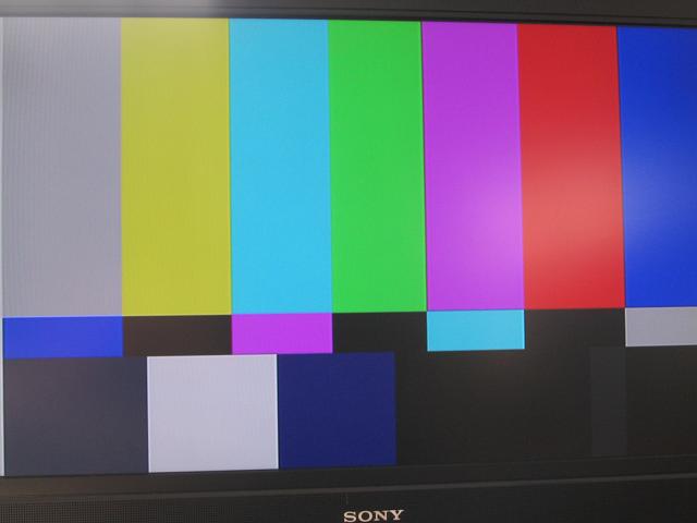
Colour bars on the Ferguson CRT TV. The moire pattern was due to the difficulty of photographing a CRT TV.

Fault finding
Now that I had a stable setup I set about injecting faults to see what happens.
The first test was to disconnect the blank signal (pin 16 of the SCART)
The display went black.
If I switched the CSYNC source from the TTL CSYNC of the Amiga, to the Composite video output of the Amiga,
I had an image, albeit a crap one!
The next test was to change the voltage on the SWITCH (pin 8 of SCART)
9-12V = RGB, 4:3 aspect ratio
3-7V = RGB 16:9 aspect ratio
0-2V = TV
So when making a cable, ensure you have 9-12V at pin 8 of the SCART lead and that the blank signal (pin 16) is 1-3V.
Loss of CSYNC, from any source, lead to a black screen.
If the TV just shows a blue screen, it is not receiving a sync signal, if after making some changes to the cabling, the
screen changes from blue to black, something has been detected but the image is not being displayed for another reason.
Check the voltages on pins 8 & 16.
Conclusion
I originally wrote this as a posting on the English Amiga Board, as a response to the numerous queries relating to
problems connecting an Amiga to a TV via SCART. The original discussion is here: eab.abime.net/showthread.php?t=47281
To come up with the most comprehensive solution, the cable was tested every TV available. In addition, the specifications of the SCART socket were checked to ensure that the impedance of the SCART signals were taken into account when calculating the control signals, SWITCH & RGB mode.
The information on the Video decoders was taken from the Analog Devices ADV7184 datasheet, available from
www.analog.com/en/analog-to-digital-converters/video-decoders/ADV7184/products/product.html
The connection diagram in the back of the datasheet was very helpful in understanding what the device expects when used in SCART RGB mode.
To summarise, this cable should work with all modern LCD televisions and older CRT TVs.
Post testing note
Since the initial testing was undertaken in September 2009, I have replaced all the electrolytic capacitors in my A600 which was used in the testing. A total of five capacitors had failed, 3 on the power supplies and 2 related to the audio circuitry. I have not had the time to re-test the composite video output to see if it has improved after the capacitor replacements.