Audio Mixer Mark II
Current Status: Complete
Date: January 2013
License: Creative Commons Attribution 3.0 Unported License
Note, PCBs are not available from this website. You can download the Gerber files from Github, https://github.com/istedman/Audiomixer
Overview
Presented here is a tested design for a single supply Audio mixer. It accepts two line level audio inputs, each with
independent volume controls. One input, can be adapted to the ‘harsh’ left/right mix of the audio output of the
Commodore Amiga computer. It crossfades the audio between the left/right channels, to improve the audio mix,
when listening on headphones. In addition it supports a ‘Better Paula’ filter circuit, claimed to improve the frequency
response of the original computer. All options are configurable.
Design information
Production standard PCB photos (files available on Github)

Schematic diagram is shown below

PCB layout
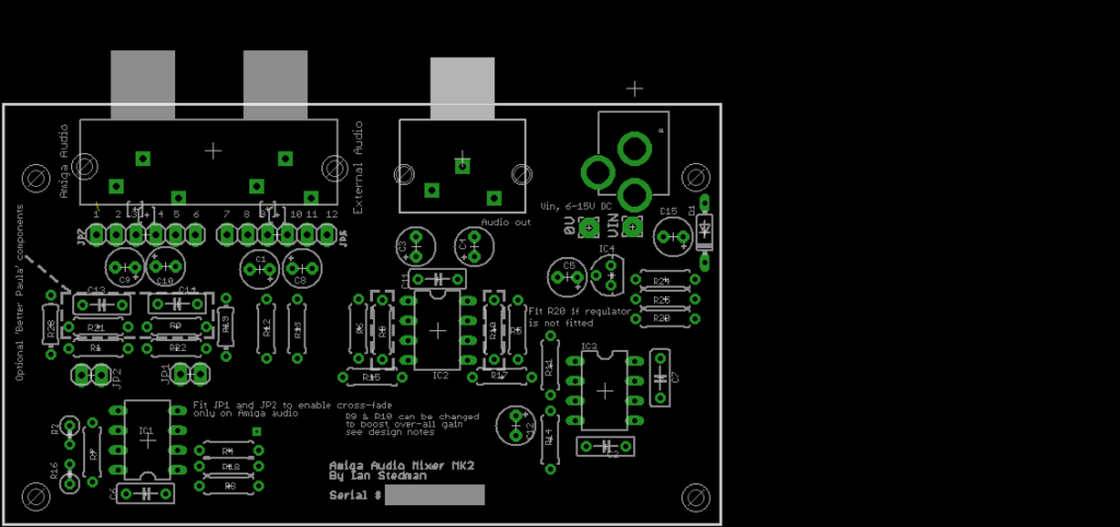
The design is fully AC coupled.
Jumpers JP1 and JP2 must be connected to cross-fade the Amiga audio. This adds ~30% of the audio from each channel.
You can download the original Eagle CAD schematics and PCB artworks here:
https://github.com/istedman/Audiomixer
Detailed assembly guide
The detailed assembly guide is available here
Audio samples
Rather than try and describe the audio mixer, MP3 samples of the original and mixed audio are presented here. The Spaceballs State of the Art and Sanity ARTE demos were used on the author’s Amiga A600, the audio recorded in 16 bit clarity by a C-media 8738 sound card.
Initial loading section of State of the Arte Demo
Original amiga audio, State of the Arte Demo, 640K
Cross-faded audio, State of the Arte Demo, 638K
Sanity Arte Demo
Original audio, Sanity_Arte demo 967K
Cross-faded audio, Sanity Arte demo 1024K
Better Paula audio, without cross-fading, Sanity Arte Demo 970K
Batter Paula audio, with cross-fading, Sanity Arte Demo 974K
In the author’s opinion, the original audio, with cross-fading sounds best, the ‘Better Paula’ circuit makes the sound too ‘tinny’ when listened to on my Sennheiser HD-205 headphones, via my Denon DF88 Hi-Fi.
Specifications
Input power supply 6-15V DC
Power consumption 9mA @ 12V DC input or 7mA with a 12V input and the 8V regulator utilized.
The measured frequency response was 15Hz to 40 KHz
The crosstalk between channels was measured as -55dB.
Circuit description
The design presented here is a classic audio mixer circuit, it utilizes a single supply operational amplifier to mix the two inputs and
provides a wide frequency response.
All inputs and outputs are AC coupled, this is required to allow a wide range of equipment to be inter-connected and also to ensure that the single supply op-amps do not get upset by a DC bias.
The design can support either fixed level, or adjustable audio inputs. By default, both inputs are set as weighted as 1:1 matching, if this is acceptable, you can bridge SJ1-SJ4 and avoid expensive dual gang logarithmic (LOG) potentiometers. If one input seems louder than the other, you can remove the solder jumpers and add a potentiometer to allow adjustable levels. The other option is to change either R12/R13 or R1/R3. Increasing the resistor values, will reduce the volume, likewise, decreasing the resistance will increase the volume. Expected values are 5-20K. A good explanation of the basics of a summing amplifier, which is created by IC1A and IC1B is here: www.electronics-tutorials.ws/opamp/opamp_4.html
The overall gain of the circuit can be changed by changing the values of R9 and R10. This module is designed to provide line level inputs to an power amplifier or powered speakers. The definition of line level varies by equipment but is typically a signal of <2V peak to peak. Increasing the gain too high will force the audio outside the levels. By default the design has unity gain set by R9/R7 for IC2A and R10/R8 for IC2B, both amplifiers are classic inverting amplifiers. The maximum gain I would use is 2x.
The module has two power options, either a 6-15V DC input or an optional 8V regulator. A 12V supply is readily available inside a PC from an ATX power supply. It was whilst testing the original prototype with an ATX supply that the 8V regulator was added. It was observed that the +12V supply from had a large amount of ripple, with a frequency of 250Hz, this was affecting the audio slightly.
Whilst I could have created an LC filter for low frequency DC noise, a simple solution, for frequencies upto a few hundred KHz is to use a linear regulator. The Power Supply Rejection Ratio (PSRR) of the regulator effectively removed the PSU noise. Note, when using the 8V regulator, the minimum supply voltage is 9.5V.
An 8V power supply was chosen to provide sufficient headroom for the largest possible signal amplitude, after taking into account the common mode range of the LM358 Which is Vcc-1.5V. This means the circuit can pass a 6.5V signal without clipping, though in practice it will be <2V. The module was tested with a 5V supply and a 2.2V worst case signal from the Amiga, the output was starting to clip, most notably at the higher frequencies. a 6V minimum supply voltage was sufficient.
Jumpers JP1 and JP2 provide the ability to mix the left and right audio inputs of the Amiga input only. Approximately 30% of the signal from the other channel is added into the summing amplifier, this reduces the harshness of the left/right audio output of the Amiga, most notably when listening via headphones. You can simply fit or remove the jumpers to see which option you prefer.
This module will not drive a pair (or single) of loudspeakers, it is intended to connect to a power amplifier or powered speakers.
The final option provided by the circuit is the ‘Better Paula’ option. This requires changing the following resistors:
Remove R1 and R3.
Change R19 and R23 from 33K to 4K7 or 5K1.
Fit JP1 and JP2.
This design was always intended to be available as a kit of parts and to make it easy to assemble, all components are through hole and available from multiple vendors.
Guideline cost, components as shown, should cost less than £8. PCB will cost £4.
Suppliers:
Spiratronics, www.spiratronics.com
CPC, www.cpc.co.uk
Rapid Electronics, www.rapidonline.com
ESR Electronic Components, www.esr.co.uk
| QTY | Value | Reference | Package | Description | Spiratronics P/N | CPC P/N | Rapid P/N | ESR P/N |
| 2 | 1u | C5, C15 | E2.5/5 | 1uF 50V electrolytic capacitor, 2.5mm pitch | FF4-690 | 11-1552 | 788-073 | |
| 6 | 2u2 | C1, C3, C4, C8, C9 C10 | E2.5/5 | 2.2uF 50V electrolytic capacitor, 2.5mm pitch | FF4-590 | 11-1553 | 788-077 | |
| 4 | 100nF | C2, C6, C7, C11 | C050-025X075 | 100nF ceramic capacitor, 5mm pitch | CA3-275 | 08-0235 | 871-061 | |
| 1 | 10uF | C12 | E2.5/5 | 10uF, 25V electrolytic capacitor | CJ4-154 | 11-1554 | 787-085 | |
| 1 | PSG01549 | SK1 | QUAD_PHONO | Quad Phono | FF6-880 | AV15007 | ||
| 1 | PSG01548 | SK2 | DUAL_PHONO | Dual Phono | FF6-870 | AV15006 | ||
| 3 | LM358N | IC1, IC2, IC3 | DIL08 | LM358AN Dual Operational amplifier. | YA3-036 | 82-0332 | LM358N | |
| 3 | SOCKET, 8 WAY | n/a | DIL08 | 8 pin DIL socket, turned pin | YP3-017 | 22-1720 | 110-082 | |
| 2 | PINHD-1X2 | JP1, JP2 | PIN | Pin header, 2.54 mm pitch, 2 way | PC3-016 | 22-0520 | 111-103 | |
| 14 | 10K | R1, R2, R3, R4, R7, R8, R9, R10, R11, R12, R13, R14, R15, R16, R17, R18 | 0207/7 | 10K 1/4W resistor, metal film | RB3-662 | 62-0897 | 907-110 | |
| 2 | 100R | R5, R6 | 0207/7 | 100R 1/4W resistor, metal film | RB3-252 | 62-0762 | 907-210 | |
| 4 | 33K | R19, R23, R21, R22 | 0207/7 | 33K 1/4W resistor, metal film | RB3-787 | 62-0934 | 907-333 | |
| 1 | 560R | R25 | 0207/7 | 560R 1/4W resistor, metal film | RB3-409 | 62-0804 | 907-156 | |
| 1 | 3K | R24 | 0207/7 | 3K 1/4W resistor, metal film | RB3-546 | 62-0887 | 907-230 | |
| 0 | PC16D | R19, R20 | PC16D | Dual gang 10K Log potentiometer, 16mm | TW2-030 | 65-1460 | 948-310 | |
| 1 | LM317LZ | IC4 | TO92 | Adjustable voltage regulator | YW4-018 | 47-3316 | LM317LZ | |
| 1 | 1N4148 | D1 | DO35-7 | Signal diode | DP1-015 | 47-3416 | 1N4148 |